Hammerhead Rev. D build schematic info
4 posters
Page 1 of 2
Page 1 of 2 • 1, 2 
 Hammerhead Rev. D build schematic info
I am currently starting to build a Hammerhead Rev.D metal detector kit which I purchased from Silverdog in U.K. Being a newby to building kits I decided to build a bog standard machine straight from the schematic. I have begun by identifying and labelling each component supplied in the kit and started to segregate the components into the sections as required by the schematic, all was ok until I got to R14 which is drawn as being parallel with R 11. I have not been able to find any reference to R14 in the text and is an addtion since Rev.c. I was assuming that R14 should be the of the same value as R11 (680 ohms)can anyone give me any info regarding this before I go ahead and make a stupid error also I am only doing the build testing with only a DVM, any info would be greatly appreciated.
Davem
Davem
Last edited by Dave.m on Fri Aug 01, 2014 6:42 pm; edited 1 time in total (Reason for editing : Spelling error)
Dave.m- Contributor

- Number of posts : 23
Age : 77
Registration date : 2014-04-21
 Re: Hammerhead Rev. D build schematic info
Hi Dave M
The purpose of the parallel resistors is for damping(prevents ringing)when the current to the coil is switched.Ringing happens because the coil(inductor) combines with the capacitance of the coil,lead etc to form oscillations.
Forget about the fact there are 2 resistor placements (R11 and R14).Think of it as a single resistor.The kit is supplied with a 680ohm 0.5watt.This is for the coil made as per the kit.You only need this one if you build that coil.If you use an after market coil then find the value for that coil from the manufacturer or experiment.The idea of the 2 positions is you can combine 2 values to get a closer match for damping.It also increases the power rating to 0.5watt(2x0.25) as they get hot.The value should be between 200ohm-800ohm.The correct value should give you best sensitivity.
Hope this help its my best explanation.
Steve
deutran- Contributor Plus

- Number of posts : 1841
Age : 60
Registration date : 2009-09-26
 Hammerhead Rev. D build schematic info
Thanks Steve for the info which you explained in simple terms that I could clearly grasp.Thanks again it was very much appreciated.
Cheers
Dav.m
Cheers
Dav.m
Dave.m- Contributor

- Number of posts : 23
Age : 77
Registration date : 2014-04-21
 Re: Hammerhead Rev. D build schematic info
Hi Dave.M
Hope you do well let me know.I was thinking a while back of doing this kit as its excellent for experimenting on.Happy to assist if I can help.
Regards Steve
Hope you do well let me know.I was thinking a while back of doing this kit as its excellent for experimenting on.Happy to assist if I can help.
Regards Steve

deutran- Contributor Plus

- Number of posts : 1841
Age : 60
Registration date : 2009-09-26
 Re: Hammerhead Rev. D build schematic info
Hi Dave no more posts since August , i m really interested in how it is going
i can help with the electronics
i can help with the electronics
Ronk- Contributor

- Number of posts : 22
Registration date : 2014-09-22
 Hammerhead Rev D progress
Sorry for not updating regularly on the progress of the Hammerhead build. I created a problem for myself in the build after I had actually completed the first phase achieving the correct voltages and then continued on and made an error by changing my mind about which potentiometers that I wanted to have an external adjustment. I was removing trim pot R2 and tore the solder ribbon on the board. I had it repaired but have ordered a new PCB from silverdog. I have also purchased all of the other components to rebuild the board.
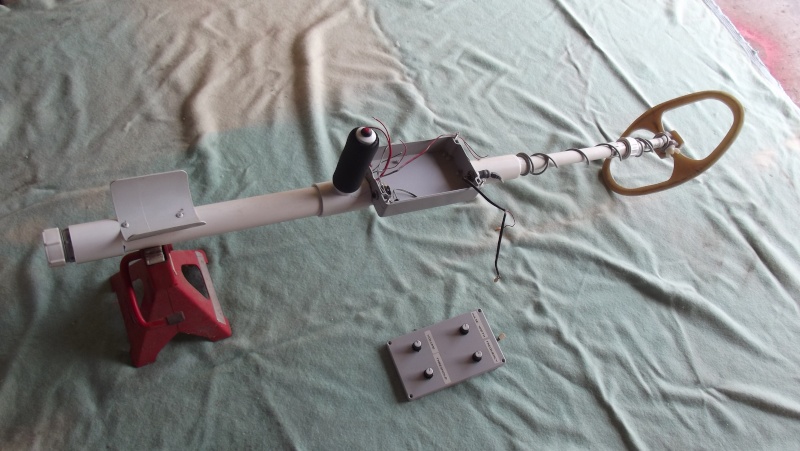
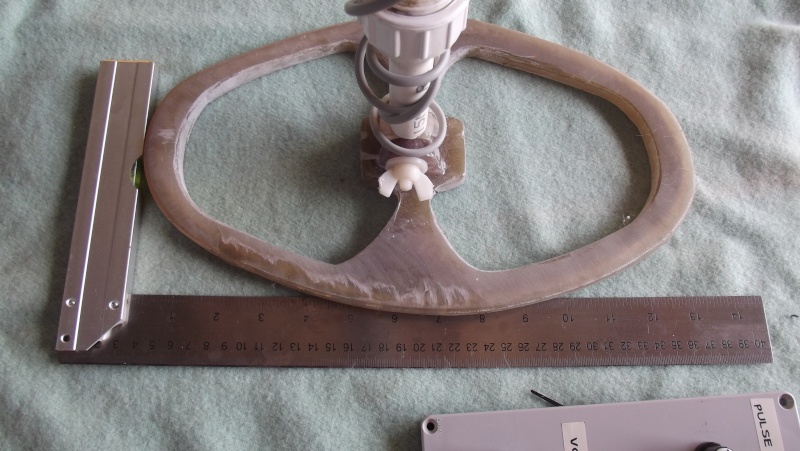
While I have been waiting I have completed the mono coil and wiring, it's a 10 inch dia. of 19 turn .5mm enamelled copper wrapped in 2 layers of 1/4 cable wrap with an aluminium tape shield and a piece of .5 stripped copper wire wrapped from one end to the other securing the
shield and providing a means to wire the shield to the board.The coil is encased in polyester resin in an eliptical shape. I am going to use a 390 ohm damping resistor.
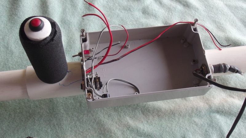
The body of the unit encases the battery pack which I have built out of plastic irrigation piping encasing the three 3.7 lion batteries which can be replaced wihout using tools in the field.I have also decided to use Eric Fosters suggestion of changing the values of c8 and c9 as well as reducing the pulse timings as suggested by the author. Now that I have made the decision on what to aim for all I have to do is wait for the new board which should be here any day now. Will keep you posted
Cheers
Dave.m
Dave.m- Contributor

- Number of posts : 23
Age : 77
Registration date : 2014-04-21
 Re: Hammerhead Rev. D build schematic info
Dave.m wrote:Sorry for not updating regularly on the progress of the Hammerhead build. I created a problem for myself in the build after I had actually completed the first phase achieving the correct voltages and then continued on and made an error by changing my mind about which potentiometers that I wanted to have an external adjustment. I was removing trim pot R2 and tore the solder ribbon on the board. I had it repaired but have ordered a new PCB from silverdog. I have also purchased all of the other components to rebuild the board.
While I have been waiting I have completed the mono coil and wiring, it's a 10 inch dia. of 19 turn .5mm enamelled copper wrapped in 2 layers of 1/4 cable wrap with an aluminium tape shield and a piece of .5 stripped copper wire wrapped from one end to the other securing the
shield and providing a means to wire the shield to the board.The coil is encased in polyester resin in an eliptical shape. I am going to use a 390 ohm damping resistor.
The body of the unit encases the battery pack which I have built out of plastic irrigation piping encasing the three 3.7 lion batteries which can be replaced wihout using tools in the field.I have also decided to use Eric Fosters suggestion of changing the values of c8 and c9 as well as reducing the pulse timings as suggested by the author. Now that I have made the decision on what to aim for all I have to do is wait for the new board which should be here any day now. Will keep you posted
Cheers
Dave.m
Hmmm!
 drawing on my vast electronic knowledge
  however for the not so electronic minded among us(me), some pictures would be a good thing if your up for sharing.
Wayne.

Digginerup- Contributor Plus

- Number of posts : 2399
Registration date : 2012-05-17
 Re: Hammerhead Rev. D build schematic info
thanks f or the update Dave I have just made a new pcb for the hammerhead and will start to build it soon
and yes i agree any pictures would be great
cheers Ron
and yes i agree any pictures would be great
cheers Ron
Ronk- Contributor

- Number of posts : 22
Registration date : 2014-09-22
 Hammerhead Rev D progress photos
Another apology as i have been unable to download my photos of my incomplete detector on this forum. I have been trying for two hours now without success and its time for a break.
Last edited by Dave.m on Wed Nov 19, 2014 3:24 pm; edited 1 time in total (Reason for editing : spelling error)
Dave.m- Contributor

- Number of posts : 23
Age : 77
Registration date : 2014-04-21
 Re: Hammerhead Rev. D build schematic info
Hi Dave.m
How have you been trying to upload pictures?
I like using phototbucket.com
As I use my iPad most of the time.
Hope you figure it out, can't wait to see what you are building
P.s make sure under your profile/ preferance.. You have HTML and bbcode ticked to on.. Sometimes that can make a difference.
How have you been trying to upload pictures?
I like using phototbucket.com
As I use my iPad most of the time.
Hope you figure it out, can't wait to see what you are building

P.s make sure under your profile/ preferance.. You have HTML and bbcode ticked to on.. Sometimes that can make a difference.
Last edited by Jen58 on Fri Nov 07, 2014 1:38 pm; edited 2 times in total (Reason for editing : Add more)
Guest- Guest
 Re: Hammerhead Rev. D build schematic info
G'day Dave.m,
Here is a link to uploading photos.
https://golddetecting.forumotion.net/t14215-how-to-upload-the-picture-s-on-our-forum-in-pictures
Here are some more links as well. Good luck with your pics.
https://golddetecting.forumotion.net/t8442-how-to-post-pictures-on-the-forum
http://photobucket.com/
https://golddetecting.forumotion.net/t14215-how-to-upload-the-picture-s-on-our-forum-in-pictures
http://tinypic.com/
Cheers.
Mike.
Guest- Guest
 Hammerhead Rev D progress photos
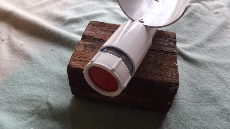
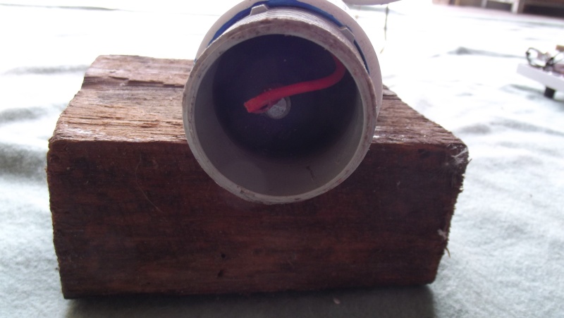
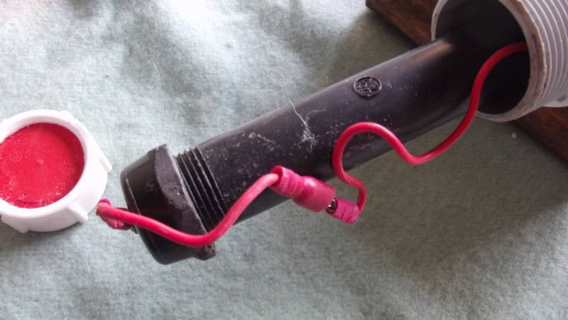
Thanks everybody for the advice on uploading I have found the problem, I had not been right clicking on paste on the LH panel. Any way here are the photos that I have been trying to send. The photos are of the coil , the overall length adjustment gland nut , the control box minus the PCB and the battery pack assy.

 [/url
[/url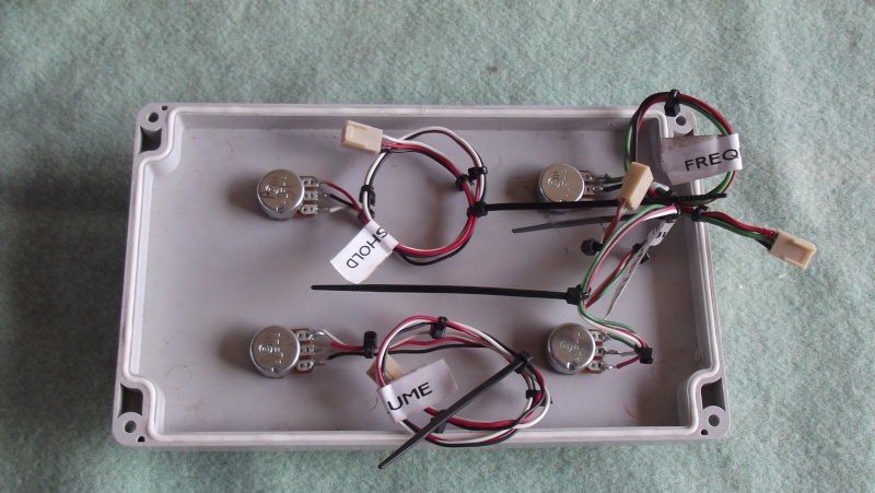 ]
]


 [/url
[/url ]
]


Dave.m- Contributor

- Number of posts : 23
Age : 77
Registration date : 2014-04-21
 Re: Hammerhead Rev. D build schematic info
Hi Dave love the photos really good stuff there
I have just ordered parts for my Hammer head from my local supplier ordered enough for 10 of each
over kill perhaps but i am sure i have a couple of sons that will want one and a mate is doing the build with me as well
cheers looking forward to your PCB pics
Ron
I have just ordered parts for my Hammer head from my local supplier ordered enough for 10 of each
over kill perhaps but i am sure i have a couple of sons that will want one and a mate is doing the build with me as well
cheers looking forward to your PCB pics
Ron
Ronk- Contributor

- Number of posts : 22
Registration date : 2014-09-22
 Hammerhead Rev D progress
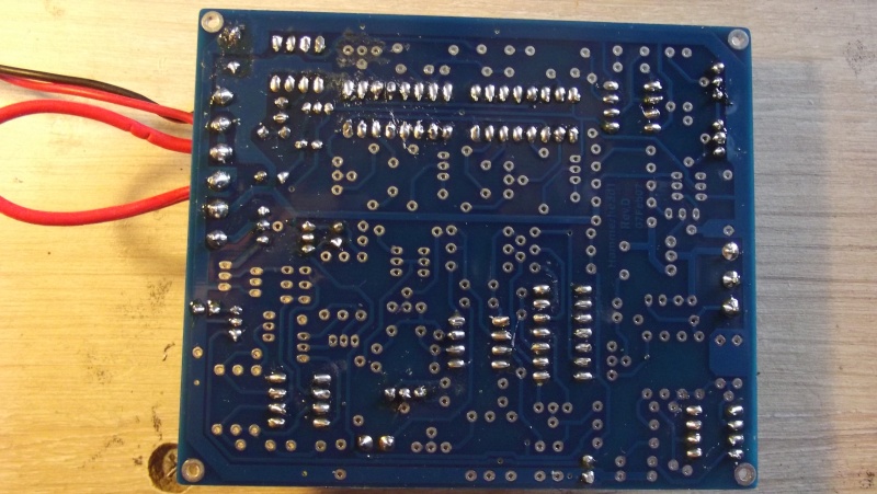
I have made a bit more progress with my PCB build up and passing the initial tests OK. The board has now been built up to the second stage of testing, here are a some more photos of the progress.
Cheers
Dave.m

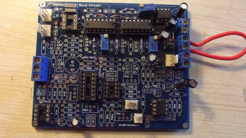
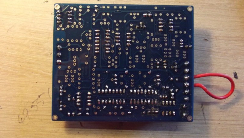
Cheers
Dave.m


Dave.m- Contributor

- Number of posts : 23
Age : 77
Registration date : 2014-04-21
 Re: Hammerhead Rev. D build schematic info
Coming along nicely, love your pipework  , never take it to the airport without declaring it in your take on luggage
  , it has a certain disconcerting appearance
  .
.
Is it possible to draw a comparison with a commercially available machine on how you hope it to perform
Wayne.
 , it has a certain disconcerting appearance
 Is it possible to draw a comparison with a commercially available machine on how you hope it to perform
Wayne.

Digginerup- Contributor Plus

- Number of posts : 2399
Registration date : 2012-05-17
 Hammerhead Rev D progress
I may be dreaming but with substitutions and options available I'm hoping it will perform as well as a Whites TDI.
Cheers
Dave.m
Cheers
Dave.m
Dave.m- Contributor

- Number of posts : 23
Age : 77
Registration date : 2014-04-21
 Re: Hammerhead Rev. D build schematic info
looking good there Dave
I have started to assemble my pcb too , will start a thread of my own soon
cheers Ron
I have started to assemble my pcb too , will start a thread of my own soon
cheers Ron
Ronk- Contributor

- Number of posts : 22
Registration date : 2014-09-22
 Hammerhead Rev D PCB progress
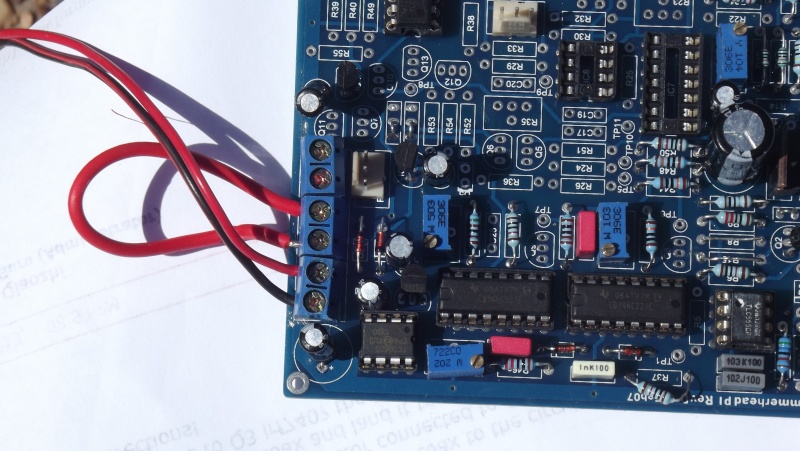
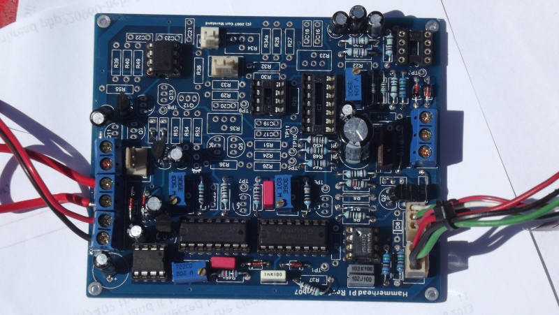
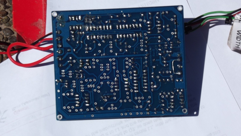
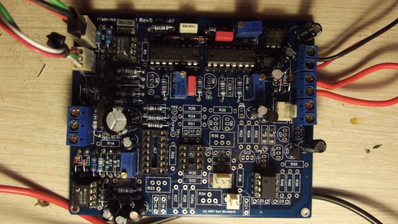
I have finally struck a snag and not a clue. At the end of testing in the clocking section after achieving the required voltages on IC5 .I could only get 0.3 of a volt max with threshold and pulse width pots being adjusted away from centre. The second problem I have is with the testing of IC6 in the transmit circuitry where I could only achieve 0.68v on pin 7 and -4.91 v on pin 4 . Other than these small problems everything is going nicely. I would appreciate everybodies inputs to the above problems.
Cheers
Dave.m
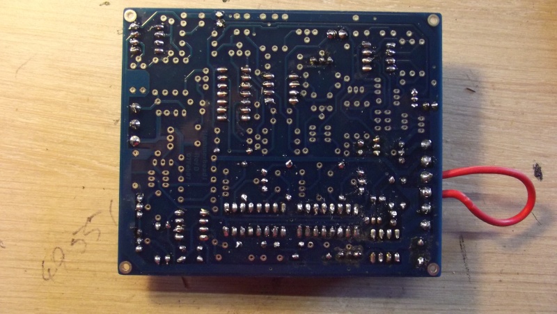 [
[ /url]
/url]
Cheers
Dave.m
 [
[ /url]
/url]Last edited by Dave.m on Wed Nov 19, 2014 3:56 pm; edited 1 time in total (Reason for editing : Incorrect photo)
Dave.m- Contributor

- Number of posts : 23
Age : 77
Registration date : 2014-04-21
 Re: Hammerhead Rev. D build schematic info
Hi Dave
Are you missing the +5V from the power supply.Check the output voltage of IC2 pin 1(or the voltage across C5).I think both problems might be related.Is D2 inserted backwards?
Steve
Are you missing the +5V from the power supply.Check the output voltage of IC2 pin 1(or the voltage across C5).I think both problems might be related.Is D2 inserted backwards?
Steve

deutran- Contributor Plus

- Number of posts : 1841
Age : 60
Registration date : 2009-09-26
 Hammerhead Rev D PCB progress
Hi Steve,
I have rechecked all of the diodes for polarity and all seem to be in the correct position, I then checked IC2 pin 1 for the correct voltage the result being -.67v. I then checked C5 and came up with the same value. I then rechecked IC6 pin 4 which was -4.86v and pin 7 was -.68v. I'm afraid I can't shed any more light on the situation. The last photo that I posted is the PCB as it is with the problem.
Cheers
Dave.m
Dave.m- Contributor

- Number of posts : 23
Age : 77
Registration date : 2014-04-21
 Re: Hammerhead Rev. D build schematic info
Hi Dave the output of ic5 is at TP1 this is a pulse of 0v to -5 v and is best looked at by a cro as a multimeter would give lower than 5v depending on pulse width
ic6 is an op amp and is used to amplify the signal coming in from the coil it should be pin 7 rail voltage +10v with respect to pin 4 of ic6 remove the ic and check voltage it should then read 10v if not you have a short on ic socket check soldering
if you only have 5 volts then check neg supply is working ic4 or ic3 both the same thing (in my circuit) rev1.5
and just to let you know some closer up pics would help for any of looking to see if you have a part in wrong or missing
hope this helps
Ronk- Contributor

- Number of posts : 22
Registration date : 2014-09-22
 Re: Hammerhead Rev. D build schematic info
Hi Dave just a thought all power supplies must be working for any of the rest to work
the 2 negative 5 volt supplies are simple 7905 dc to dc converter
but the positive 5 volt supply is a little more complicated and the 7660 and c3 c4 d1 d2 make a voltage doubler that feeds the 7805 again a cro would be helpful to check the output of the 7660 if your not getting +5volt
the 2 negative 5 volt supplies are simple 7905 dc to dc converter
but the positive 5 volt supply is a little more complicated and the 7660 and c3 c4 d1 d2 make a voltage doubler that feeds the 7805 again a cro would be helpful to check the output of the 7660 if your not getting +5volt
Ronk- Contributor

- Number of posts : 22
Registration date : 2014-09-22
 Re: Hammerhead Rev. D build schematic info
Hi Dave
You definitely have lost the +5V.Please a close up photo of D1 and D2.If there Ok then lift one leg of R37 to enable the internal clock of 7660 and see if the +5v comes up.
N.B The -4.91 v on pin 4 is correct.
You definitely have lost the +5V.Please a close up photo of D1 and D2.If there Ok then lift one leg of R37 to enable the internal clock of 7660 and see if the +5v comes up.
N.B The -4.91 v on pin 4 is correct.

deutran- Contributor Plus

- Number of posts : 1841
Age : 60
Registration date : 2009-09-26
 Hammerhead Rev D PCB progress
Hi fellows,
Firstly thanks for all of your inputs into the problem that I have they are really appreciated. I have been carrying out the fault finding that you both have suggested and here are the results:
Output of IC5 at TP1=-0.23
Output of IC6 at pin7 = -0.68v
Output of IC6 at pin 4 =-4.86
Output of iC6 with IC removed Pin7= -.06v
Output of IC6 with IC removed Pin4=-4.95v
Output at IC4=-4.92v
Output of IC6 with IC removed and one leg of R37 lifted at Pin7=+5.0v
Output of IC6 with IC removed and one leg of R37 lifted at Pin4=-4.95v
Some new shots of D1 & D2 attached.
Cheers
Dave.m
Dave.m- Contributor

- Number of posts : 23
Age : 77
Registration date : 2014-04-21
 Hammerhead Rev D progress photos
The photos are being held up by internet explorer at the moment as it keeps on dropping out at about 70 % of the photo upload. I will try again later this afternoon.
Cheers
Dave.m
Cheers
Dave.m
Dave.m- Contributor

- Number of posts : 23
Age : 77
Registration date : 2014-04-21
 Re: Hammerhead Rev. D build schematic info
Good news Dave your getting close to solving the problem now.Sounds like there are no pulses coming from IC11 pin 2.I'll have a bit of a look and see what may cause this.

deutran- Contributor Plus

- Number of posts : 1841
Age : 60
Registration date : 2009-09-26
 Re: Hammerhead Rev. D build schematic info
Hi Dave my pcb layout is different to yours and i suspect the circuit is a bit different too i think the basic design is the same , anyway i think the first thing is to get the power supply working right ie the correct voltages at the output of the 7805 and the 7905 , my circuit has 2 7905 outputs
the way to tell if they are right is measure the volts between the middle pin and the outside pins
the middle pin is ground or common or neutral the voltage should read 5.10 volts or very close to it in my pcbs the variation is is between 5.06 to 5.13 , on the other side you should get the battery voltage and the 7805 input voltage should be about 10 volts in my opinion. the 7905 should also read the same only negative voltages
to keep it simple just measure between the pins on the 7905 and 7805 from center to each outside pin should read 10 v one side and 5 v on the other side
if the 7660 isnt oscillating then no 10volt to the 7805 remove c11 which connects to the 7660 on pin 7 and try again it should work then
i am missing parts to my pcb so cant offer much more than this until i get mine going
good luck
Ronk- Contributor

- Number of posts : 22
Registration date : 2014-09-22
 Re: Hammerhead Rev. D build schematic info
Hi Dave
I'm wondering about the pulses from the 555 timer if they are missing(N1 TP1).I see the voltage you measured is OK at -0.23V TP1 this is the lower end it should be -0.5 if the pots are centered R2 and R3.Did you receive a diode D8 in the kit.
I'm wondering about the pulses from the 555 timer if they are missing(N1 TP1).I see the voltage you measured is OK at -0.23V TP1 this is the lower end it should be -0.5 if the pots are centered R2 and R3.Did you receive a diode D8 in the kit.

deutran- Contributor Plus

- Number of posts : 1841
Age : 60
Registration date : 2009-09-26
 Hammerhead Rev D PCB progress
Hi fellows,
I have carried out your latest suggestions with the following results after removing C11 :
IC3 = 12.4v
7.5v
IC2 = 11.1v
4.99v
IC5 at TP1 = -1.1v with R2 and R3 centrally adjusted and when R3 was adjusted to either full adjustment position the voltage dropped to -0.25v.
IC6 at Pin 4 = -4.95V
Pin 7 = + 5.0v
I did find one problem which was two of the leads on the pulse width pot were crossed also there is a position for D8 on the PCB but not in the kit and not mentioned in the text. The text also states R37 and D11 may also be omitted entirely.
Cheers
Dave.m
Last edited by Dave.m on Sat Nov 22, 2014 3:46 pm; edited 2 times in total (Reason for editing : symbol omission additional info.)
Dave.m- Contributor

- Number of posts : 23
Age : 77
Registration date : 2014-04-21
Page 1 of 2 • 1, 2 
 Similar topics
» want detector schematic
» Terrano bed build.
» Updated Banjo/Highbanker Plans.
» Hammerhead Rev D progress photo
» Hammerhead detector from scratch
» Terrano bed build.
» Updated Banjo/Highbanker Plans.
» Hammerhead Rev D progress photo
» Hammerhead detector from scratch
Page 1 of 2
Permissions in this forum:
You cannot reply to topics in this forum